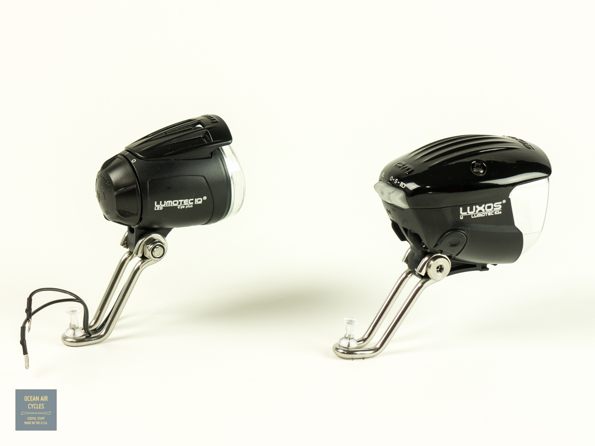
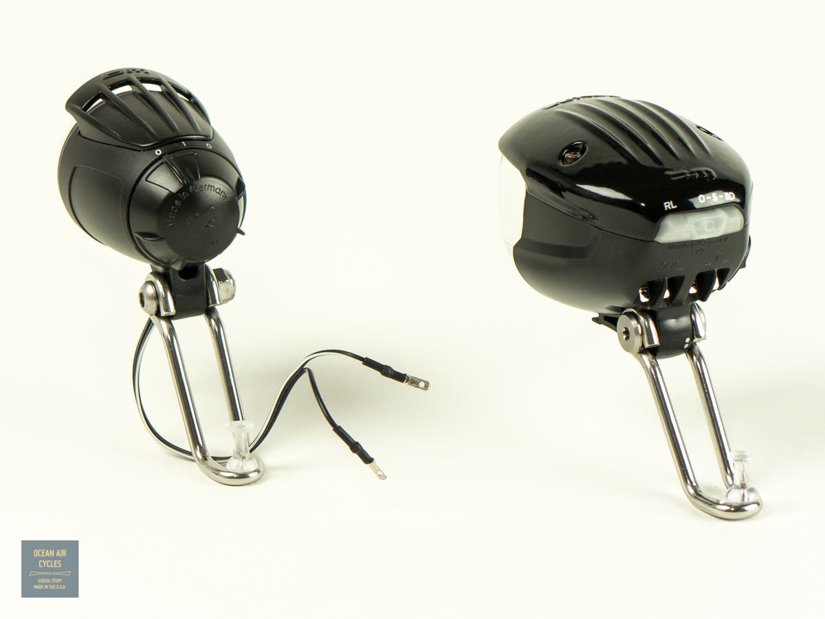
The new Busch and Muller Luxos dynamo headlights are setting a new standard for high-powered LED lighting, both in brightness and distribution of light. The Luxos U takes it one step further with a remote switch and USB charger.
All of the Luxos lights are able to be paired with a dyno powered tail light. The catch is that the tail light cannot be grounded to the frame or fender through the mounting screw. The will cause a fault circuit that detects a problem in the tail light. There will be problems with the functionality of the light and possible damage to the circuitry. This is a is a challenge because most of the popular fender mounted tail lights currently available offer the option of grounding through a wire or the mounting screw. My current favorite for both function and looks has been the B&M Seculite plus.
 I had already gotten my sample Luxos wired up and going when I became aware of the issue with a grounded tail light. At first I was a little bummed, then the challenge was set, and I decided to figure out how hard this was going to be to fix. It turned out to be fairly simple, and I have outlined the steps here for you.
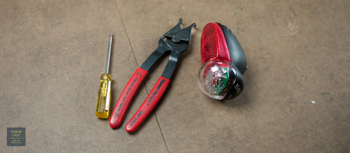
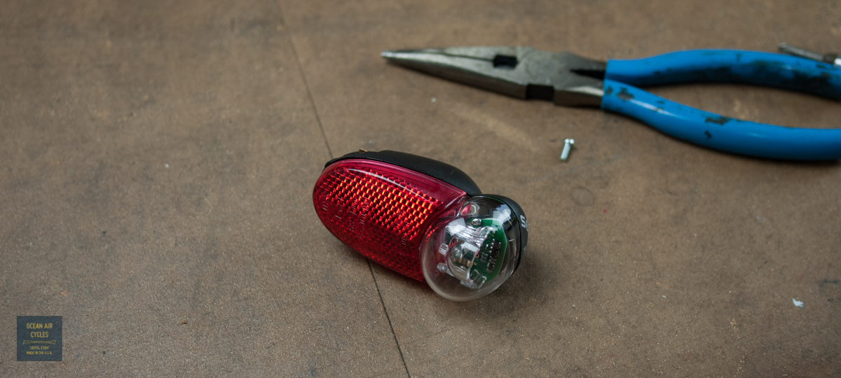
You will need a few basic tools: small flat head skew driver and small wire cutters will get you there, cir-clip pliers and a small Phillips head screw driver help make things a little easier.
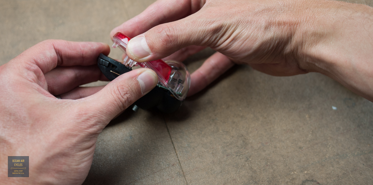
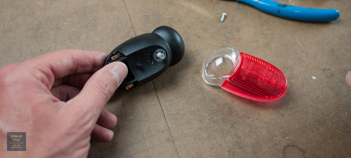
 The first thing I did was remove the nuts and washer from the mounting screw. The first is the standard hex mounting nut. Then there is the round washer style nut that holds the bolt to the light body
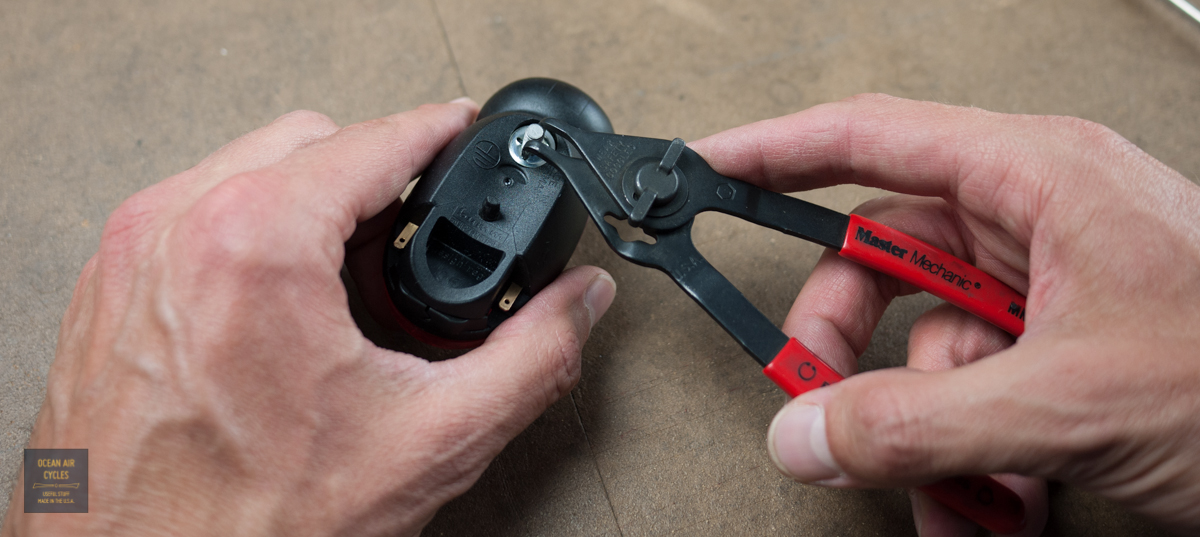
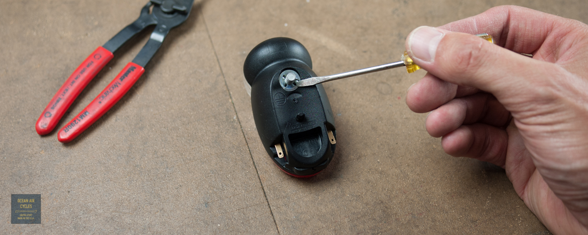 You can get this one off by carefully pushing it around counter-clockwise with the tip of your flat head screwdriver, but the cir-clip pliers made it a little easier.
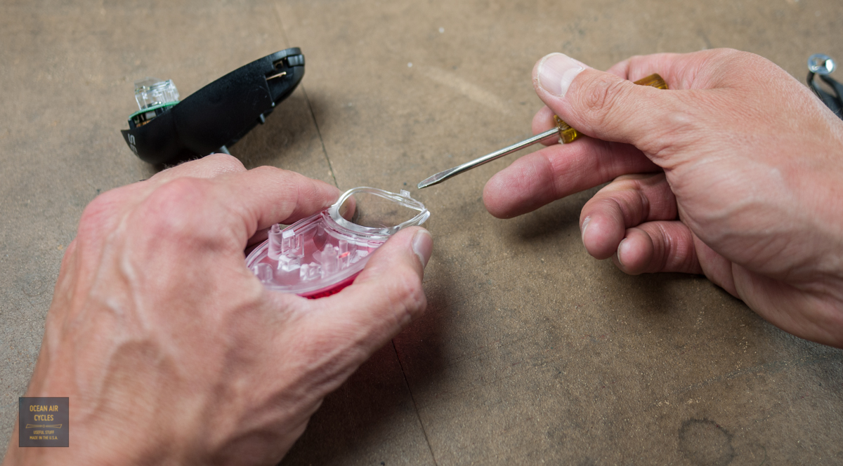
Once done you will be opening the light housing. Carefully work your way around the edges, starting from the bottom. The two halves of the housing are a press/snap fit together and can come apart safely as long as you are careful. I inserted the tip of the screwdriver into the thin gap between housings and lightly twisted to get it going.


As you approach the top you need to be extra careful. This is where there is a small tab that indexes the two halves together. At this point I stopped using the tool and gently separated the two halves with my hands
 Once opened, you can easily see the above mentioned plastic tab.
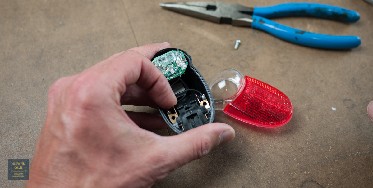
 Moving on to the grounding of the light. The Seculite plus has two possible grounding paths. For most common installations involving a B&M headlight you will be wiring the tail light tot he front with a paired or co-axial conductor. The other grounding path is through the mounting screw. This is only used in cases where the frame of the bike and associated hardware are used as the grounding path. looking at the circuit board you can see both of the internal grounding wire options on the left side. The single wire on the left is for the positive lead.
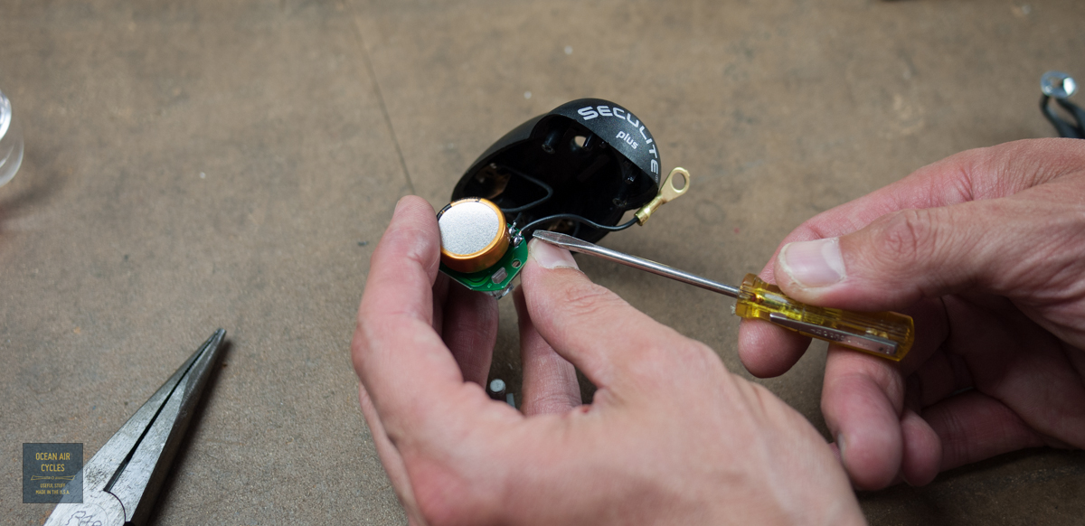
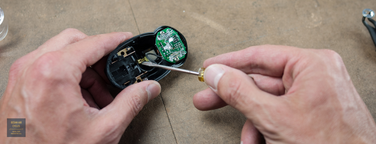 The grounding wire to the frame mount needs to come out. It is connected to the mounting bolt with a ring connector. I was able to get the bolt out of the housing with the LED circuit board in place. If this is too tight for your comfort, you can remove the two Phillips head screws securing the board to the housing and you will then have plenty of room to work.
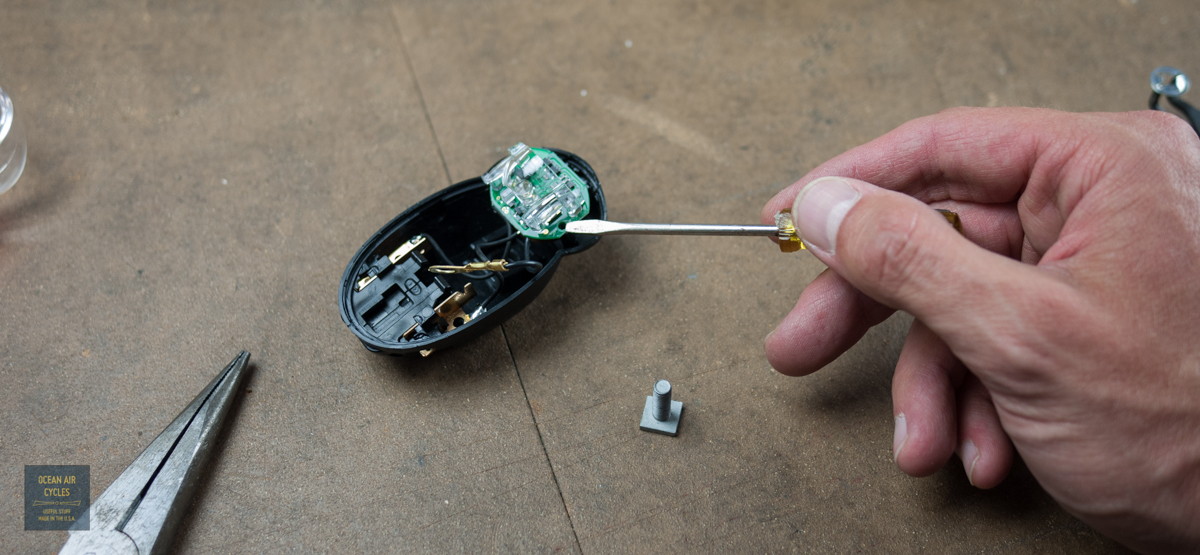
 With the board out, you will want to snip the wire with the ring connector as close as you can to the board.
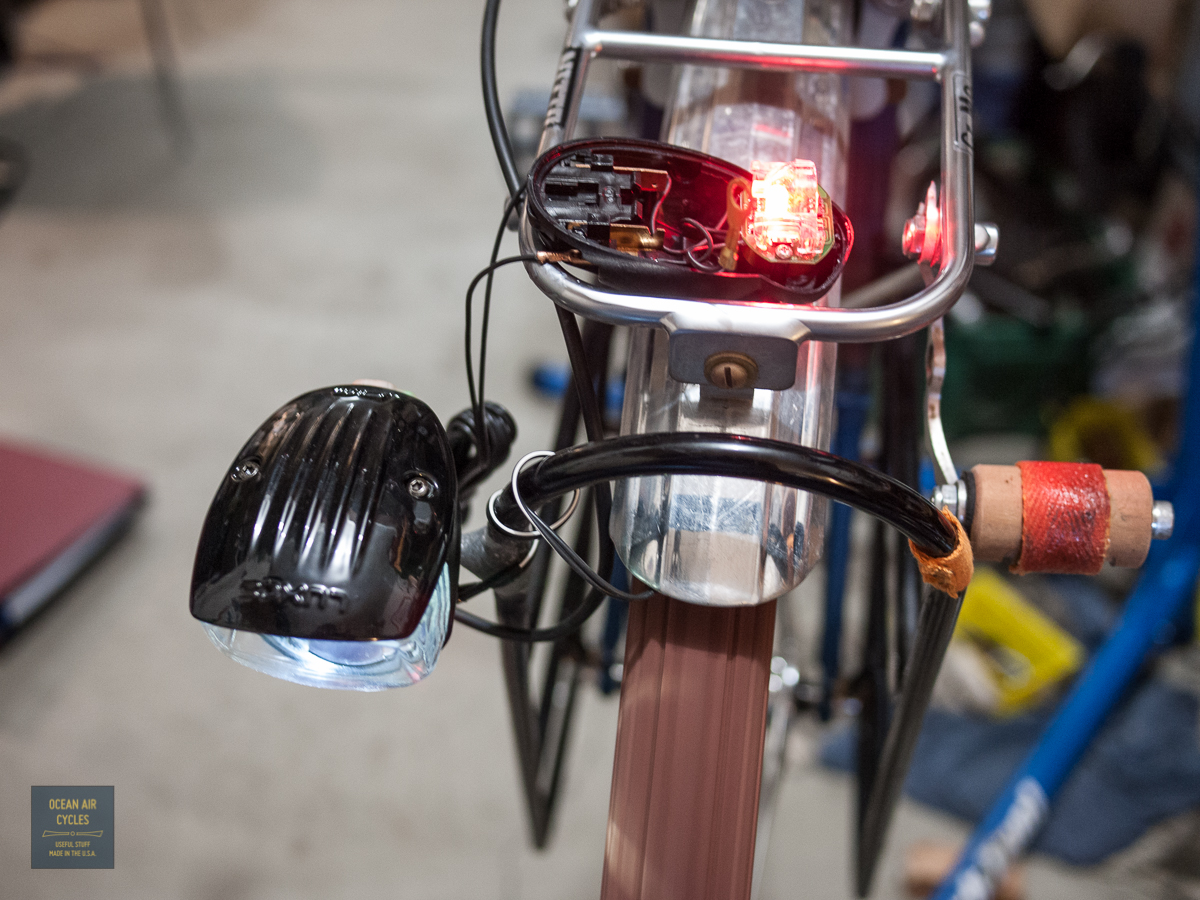
 In theory you could leave the connector inside and isolate it, wrap it in electrical tape or shrink wrap, so that the process could be reversed. For this light I am pretty certain that it will never be wired with a frame ground path, so I snipped. While I had things appart I wired the Seculite into the Luxos U and confirmed that everything was as hoped.
The re-assembly is a pretty straight forward reversal of the above steps. Double check that the remaining wire connection points are fully seated in the housing.
 Insert the mounting bolt and fasten in place with the thin nut.
 Carefully align the two housing halves and squeeze together, they should snap into place and the light is ready for wiring and mounting to the bicycle as usual
For the home mechanic that is comfortable with electrical work this is not too bad of a project to take on. If you feel that this is above your skill level, and want a Luxos Seculite combo from us, I am more than happy to perform this procedure for free.